MTA
for Line-Line Fault
Consider a part of the power system as
shown in the figure. Let there be Line-Line fault at point A and let direction
decision to be made by the relay at point B.
When
there is no fault; vector diagram representing voltage and current is as shown
in figure.
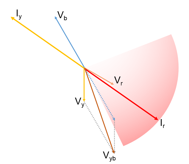
For
R-Y fault R-Ph and Y-Ph source voltage will decrease and will approach close to
each other and R-Ph current will lag approximately 900 with respect
to R-Y Phase voltage thus during fault vector diagram will be as shown in
figure.
Thus
depending up on nature of load and fault impedance R-Phase current may be
anywhere as shown by shaded area for figure.
Obviously voltage selected for this
direction decision making will be of healthy phases. That means if we are
considering direction decision making in respect of R-Ph current then we have
to choose VYB voltage as our reference voltage as shown in figure.
To include all this probable area for
R-Ph current it is necessary to redefine zone of forward direction with respect
to polarizing voltage VYB. Thus line AB is selected as new dividing
line for operating direction (Forward) and Non-Operating direction (Reverse).
Perpendicular line to this dividing line is line C-D. Now we can see that line
CD leads VYB. For electromagnetic relays this angle use to be 450.
Now for numerical relay this angle is settable still recommended value is +450.


No comments:
Post a Comment